Der DCW 2.2 Bindemittelverteiler Die erste Maschine, die bei jedem koreanischen FDR-Verfahren (Full-Depth Reclamation) zum Einsatz kommt, ist die THOR ST. Sie bringt trockenes, körniges Stabilisierungsbindemittel mit der exakt geplanten Menge auf die Fahrbahnoberfläche auf, bevor es vom Fräsvorgang der Bodenstabilisierungsmaschine in das Tragschichtmaterial eingemischt wird. Ohne präzise Bindemittelapplikation kann das FDR-Verfahren keine Tragschicht mit gleichmäßiger Tragfähigkeit über die gesamte Behandlungsbreite erzeugen – selbst eine korrekt betriebene THOR ST kann eine ungleichmäßige Bindemittelverteilung nicht ausgleichen.
Dieser Leitfaden behandelt die Spezifikationen des DCW 2.2 im Detail, erklärt die Gründe für die Frontmontage und die obligatorische Ballastmenge von 1.300 kg, beschreibt das elektronische Kabinensteuerungssystem, das eine genaue Einstellung der Streumenge ohne Berechnung durch den Bediener ermöglicht, erläutert den internen Zweiwalzen-Streumechanismus und bietet die praktischen Bedienungsverfahren für FDR-Anwendungen auf koreanischen Straßen.
Bestätigte Spezifikationen des DCW 2.2 – Aus der offiziellen Watanabe-Broschüre
Alle Spezifikationen stammen aus der offiziellen Produktbroschüre von Watanabe.
Warum Frontmontage? – Die Funktionsweise des FDR hinter der Konfiguration
Die Frontmontage des DCW 2.2 ist nicht willkürlich, sondern durch die Betriebssequenz des FDR-Verfahrens vorgegeben. Bei einem standardmäßigen koreanischen FDR-Verfahren ist der Bodenstabilisator THOR ST die Hauptarbeitsmaschine und wird am Heckkraftheber hinter dem Traktor gezogen. Der DCW 2.2 muss vor dem Fräsvorgang des THOR ST Bindemittel auf die Fahrbahnoberfläche aufbringen – daher muss er vor dem Traktor montiert sein, nach vorne gerichtet, und während der Fahrt des Traktors Bindemittel auf die unbehandelte Fahrbahnoberfläche aufbringen. Die Logik der Sequenz:
Die obligatorische Ballastmenge von 1.300 kg – Warum sie nicht verhandelbar ist
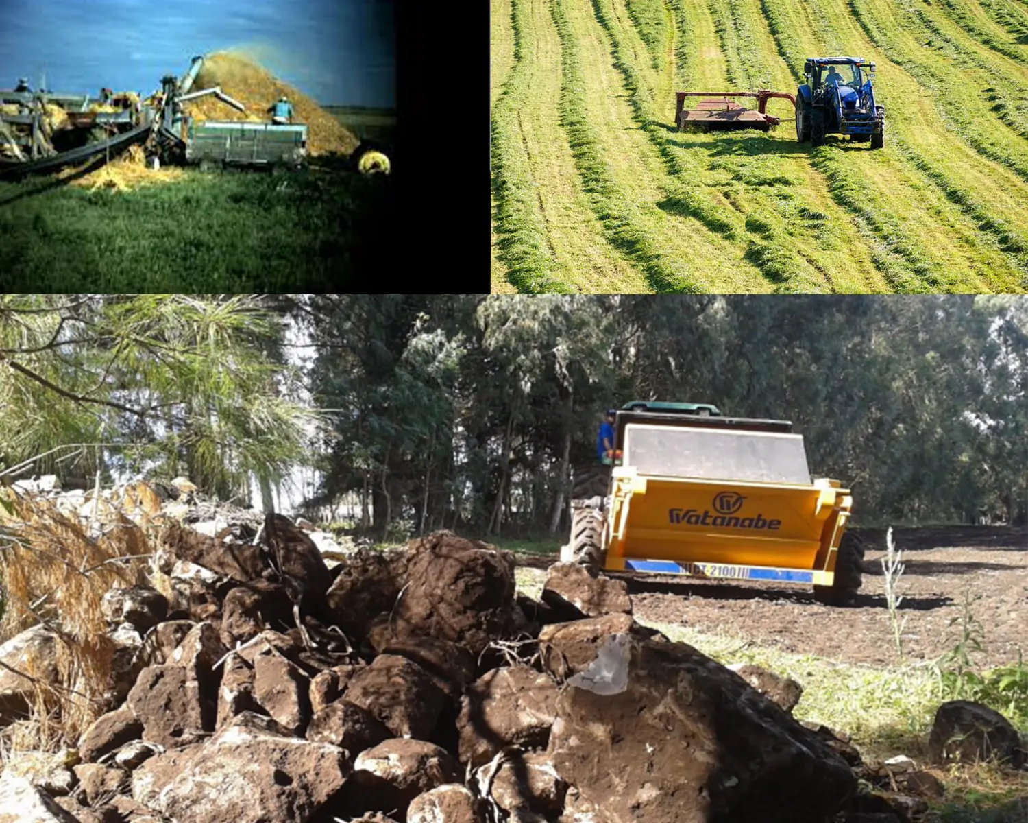
Die vorgeschriebene Ballastmenge von 1.300 kg für den DCW 2.2 wird bei der Planung von FDR-Projekten in Korea am häufigsten übersehen – und hat bei Missachtung die unmittelbarsten Sicherheitsfolgen. Um zu verstehen, warum diese Vorgabe zwingend ist, muss man die Lastverteilung auf einem Traktor kennen, der gleichzeitig den DCW 2.2 vorne und den 5.300 kg schweren THOR ST hinten trägt.
Ohne 1300 kg Ballast – Überlastung der Hinterachse und Lenkungsverlust
Ein Traktor mit 250 PS und CVT-Getriebe hat ein Gesamtgewicht von ca. 12.000–15.000 kg, wobei die Gewichtsverteilung in der Standardkonfiguration ca. 601 TP5T hinten und 401 TP5T vorne beträgt. Durch die Montage des THOR ST (5.300 kg) an der Heckhydraulik verschiebt sich die Gewichtsverteilung deutlich nach hinten – potenziell auf 75–801 TP5T. Bei dieser Verteilung sinkt die Vorderachslast unter die Mindestlast des Lenkreifens für eine zuverlässige Lenkkontrolle. Die Vorderreifen verlieren an Traktion und Lenkwirkung – besonders gefährlich auf nassen, weichen Fahrbahnoberflächen, wie sie für die Fahrbahnsanierung (FDR) vorgesehen sind. Der DCW 2.2 mit 1.300 kg Ballast sorgt für eine sichere Gewichtsverteilung der Traktor-Anbaugeräte-Kombination und hält die Vorderachslast während der gesamten FDR-Durchfahrt über der Lenkwirkungsschwelle.
Mit 1.300 kg Ballast – korrekte Gewichtsverteilung
Das Eigengewicht des DCW 2.2 zuzüglich des 1.300 kg schweren Ballasts (insgesamt ca. 1.800–2.200 kg an der Frontkupplung) kompensiert das Hecklastmoment des THOR ST ausreichend, um die Vorderachslast innerhalb der sicheren Lenk- und Traktionsgrenzen zu halten. Der genaue Ballastbedarf wird im Rahmen der Traktorenkompatibilitätsprüfung vor Projektbeginn ermittelt. Korea Watanabe führt diese Kompatibilitätsprüfung als Teil der Kaufberatung für den DCW 2.2 durch, um sicherzustellen, dass das jeweilige Traktormodell die Anforderungen an die kombinierte Frontlast mit dem serienmäßigen 1.300 kg Ballast erfüllt.
Elektronische Kabinensteuerung – Wie die DCW 2.2 eine präzise Ausbringungsmenge erreicht
Das elektronische Kabinensteuerungssystem des DCW 2.2 macht den Bindemittelstreuer von einem einfachen mechanischen Streuer zu einem Präzisionsdosierer. Das System regelt die Bindemittelausbringungsmenge (kg/m²) elektronisch von der Traktorkabine aus. Der Fahrer gibt die gewünschte Ausbringungsmenge ein, und das System passt den Streuerantrieb automatisch an, um diese Menge unabhängig von der Fahrgeschwindigkeit konstant zu halten. Dies ist der entscheidende Vorteil gegenüber mechanischen Streuern, die bei Geschwindigkeitsänderungen manuell nachjustiert werden müssen und Unebenheiten, die die Streugleichmäßigkeit beeinträchtigen, nicht automatisch ausgleichen können.
Funktion 1:
Einstellung und Anzeige der Rate. Der Bediener gibt die im Bindemittelrezept für das Straßenbauprojekt vorgegebene Zielmenge (kg/m²) ein. Die Steuereinheit zeigt die aktuelle Menge, die insgesamt aufgebrachte Materialmenge und das verbleibende Fassungsvermögen des Behälters an. So kann der Bediener überprüfen, ob die korrekte Menge während des gesamten Arbeitsgangs eingehalten wird und Nachfüllstopps anhand des verbleibenden Materialvolumens im Verhältnis zur verbleibenden Straßenlänge planen.
Funktion 2:
Geschwindigkeitskompensierter Antrieb. Das Fahrgeschwindigkeitssignal (vom ISOBUS-Anschluss des Traktors oder einem Geschwindigkeitssensor) wird an das elektronische Steuergerät übermittelt. Dieses passt die Drehzahl des Streuwagenantriebs an, um eine konstante Ausbringungsmenge von kg/m² bei variierender Fahrgeschwindigkeit zu gewährleisten. Verlangsamt der Traktor vor Kurven oder Steigungen, wird die Drehzahl des Streuwagenantriebs proportional angepasst – so wird eine Überdosierung bei niedriger und eine Unterdosierung bei höherer Geschwindigkeit verhindert.
Funktion 3:
Ein-/Ausschalter für Vorgewendestopps. Die elektronische Steuerung umfasst eine vom Fahrerhaus aus steuerbare Start/Stopp-Funktion. Der Fahrer kann den Bindemittelfluss am Vorgewende stoppen, ohne den Traktor anzuhalten. Dadurch wird eine Bindemittelansammlung an den Straßenenden verhindert, wo der THOR ST nicht fräst. Dies reduziert Materialverluste und verhindert die Bildung von bindemittelreichen Stellen an den Bearbeitungsenden, die zu überbefestigten Bereichen führen würden, welche nicht dem geplanten Profil entsprechen.
Zwei Innenrollen (1 m / 2 m umschaltbar) – Anpassung an die Straßenbreitenverhältnisse in Korea
Die DCW 2.2 verwendet zwei interne horizontale Walzen, um das Bindemittel aus dem Vorratsbehälter zu dosieren und gleichmäßig über die 2.140 mm Arbeitsbreite zu verteilen. Die umschaltbare Walzenkonfiguration (1 m/2 m) ermöglicht es dem Bediener, das Streubild an die unterschiedlichen Straßenbreiten in Korea anzupassen.
1m-Rollenkonfiguration
Beide 1-m-Walzen aktiv – maximale Durchmischung, beste Verteilung von Feinpulverbindemitteln (Branntkalk in Säcken, Feinzement). Sorgt für ein gleichmäßigeres Verteilungsbild bei Bindemitteln, die im Trichter zum Verklumpen oder Brückenbilden neigen. Anwendungsbereiche: Feinpulverbindemittel, hohe Luftfeuchtigkeit, bei der Brückenbildung wahrscheinlicher ist, oder wenn bei kritischen Straßenbauprojekten höchste Auftragsgleichmäßigkeit erforderlich ist.
2m-Rollenkonfiguration
Volle 2-m-Walze aktiv – höherer Durchsatz pro Umdrehung, besser geeignet für körnige Bindemittel (groberer Trockenzement, Bindemittelmischungen, Flugasche). Ermöglicht schnelleres Auftragen bei hohen Auftragsmengen (über 4 kg/m²), wo die 1-m-Walzenkonfiguration die Durchsatzgeschwindigkeit begrenzen kann. Einsatzgebiete: körnige oder grobe Bindemittel, Projekte mit hohen Auftragsmengen, schnelle Bindemittelauftragsvorgänge.
DCW 2.2 Betriebsverfahren – Vorbereitung der Antragsstellung und Passverwaltung
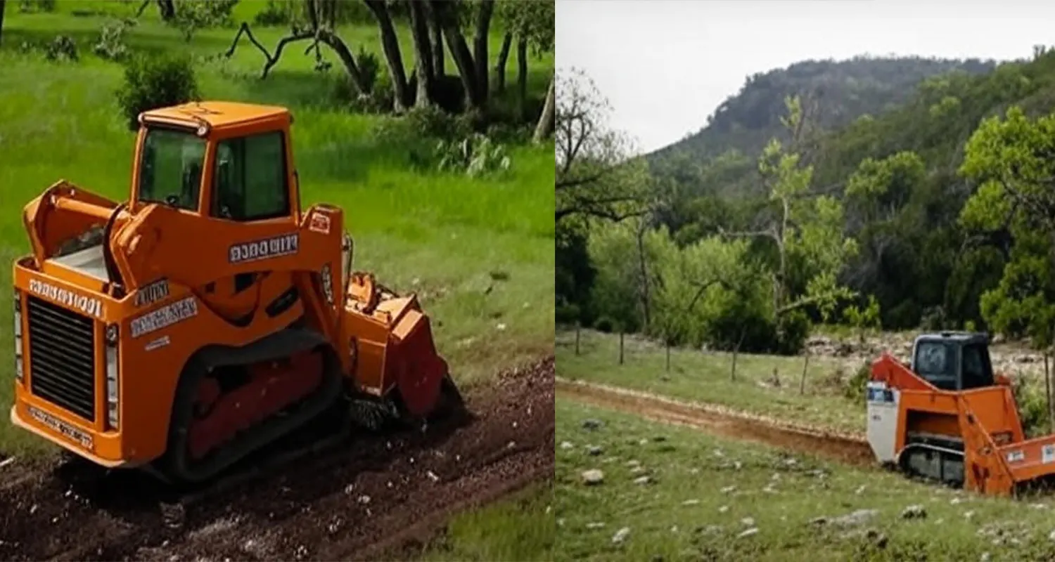
Die korrekte Einrichtung des DCW 2.2 vor dem ersten Arbeitsgang ist entscheidend, um die geplante Bindemittelauftragsmenge von Beginn des Projektabschnitts an zu erreichen. Ein nicht kalibrierter oder falsch konfigurierter Streuer führt zu Auftragsfehlern, die sich über die gesamte Projektlänge summieren. Dies hat eine Über- oder Unterstabilisierung des Untergrunds zur Folge, die erst bei der Tragfähigkeitsprüfung sichtbar wird, nachdem die FDR-Behandlung ausgehärtet ist und zusätzliche Sanierungsmaßnahmen kostspielig sind.
Vorstartprüfung 1:
Prüfen Sie, ob das Bindemittel der Spezifikation entspricht – wiegen Sie eine Probe aus den Liefersäcken oder dem Großbehälter und vergleichen Sie die Dichte mit der Dichte der Materialmischung. Unterschiedliche Bindemittelmarken können bei gleicher Nennspezifikation unterschiedliche Schüttdichten aufweisen, was die Umrechnung von Volumen in Masse bei der Kalibrierung der elektronischen Steuerung beeinflusst.
Vorstartprüfung 2:
Statische Kalibrierungsprüfung: Befüllen Sie den Behälter des DCW 2.2 mit einer bekannten Menge Bindemittel, betreiben Sie den Streuer für eine bestimmte Zeit mit der eingestellten elektronischen Steuerung und wiegen Sie die Ausbringungsmenge. Vergleichen Sie die gemessene Ausbringungsmenge mit der Sollmenge. Passen Sie den Kalibrierungsfaktor der elektronischen Steuerung an, wenn die gemessene Menge um mehr als ±5% vom Sollwert abweicht.
Vorstartprüfung 3:
Prüfen Sie die Funktion der Geschwindigkeitsregelung: Fahren Sie 10 m mit der vorgesehenen Arbeitsgeschwindigkeit (typischerweise 2,5–4,0 km/h) und überprüfen Sie, ob die Anzeige der elektronischen Steuerung den erwarteten Materialverbrauch für die zurückgelegte Strecke und Breite anzeigt. Dies bestätigt, dass die Geschwindigkeitsregelung und die Steuerung eine präzise Kompensation der Verbrauchsrate gewährleisten.
Während des Passes:
Halten Sie die Fahrgeschwindigkeit konstant – stoppen Sie den Traktor nicht in der Mitte des Abschnitts, es sei denn, der THOR ST stoppt ebenfalls. Ein Anhalten des Traktors bei laufendem Streuer führt zu einem konzentrierten Bindemittelband, das nach der Aushärtung nicht mehr korrigiert werden kann. Im Falle eines Notstopps schließen Sie gleichzeitig die elektronische Steuerklappe, um eine lokale Überdosierung zu vermeiden.
Wartung und Lagerung – Schutz des DCW 2.2 vor Beschädigungen durch den Binder
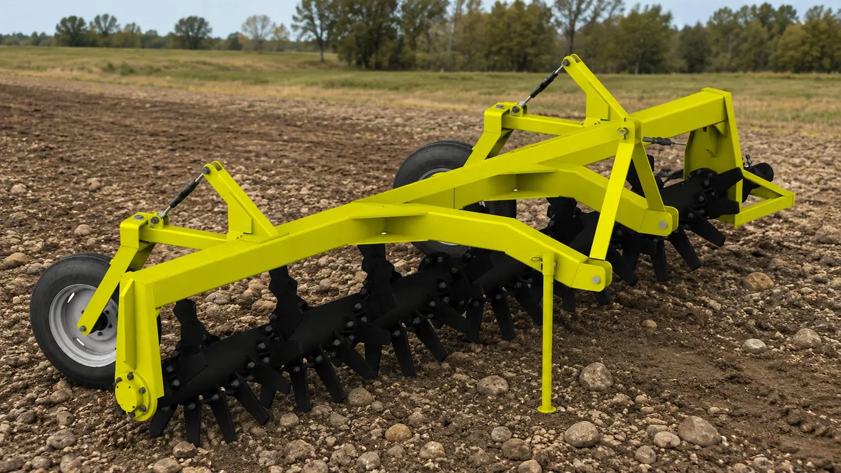
Die wichtigste Wartungsanforderung der DCW 2.2 unterscheidet sich von allen anderen Maschinen der Watanabe-Produktpalette: Nach jedem Einsatz muss sie vollständig von Bindemittelresten befreit werden. Zement oder Branntkalk, der über Nacht oder ein Wochenende im Trichter verbleibt, nimmt Luftfeuchtigkeit auf und beginnt auszuhärten. Dabei bilden sich harte Ablagerungen an den Trichterwänden, den Walzenoberflächen und dem Dosierschieber, die die Dosiergenauigkeit zunehmend verringern und im Extremfall zum Blockieren des Streumechanismus führen können.
Ende eines jeden Arbeitstages:
Entfernen Sie alle Bindemittelreste vollständig – lassen Sie kein Bindemittel über Nacht im Trichter. Geben Sie nach dem Entleeren eine kleine Menge trockenen Sand oder trockenes Sägemehl durch den Mechanismus, um verbliebenen Bindemittelstaub von den Innenflächen zu entfernen. Blasen Sie die Walzen- und Schiebermechanismen mit Druckluft aus, um feines Material aus Spalten und Lagerflächen zu entfernen.
Nach Projektabschluss (Saisonende):
Spülen Sie das System gründlich mit trockenem Sand. Schmieren Sie alle Wälzlager, die Antriebskette und die Drehpunkte des Schiebers. Prüfen Sie alle Dichtungen am Trichtergehäuse auf Risse oder Beschädigungen, die während der Lagerung Feuchtigkeit eindringen lassen könnten. Lagern Sie den DCW 2.2 an einem trockenen, überdachten Ort mit vollständig geöffnetem Trichter zur Belüftung, um Feuchtigkeitsansammlungen im Inneren des verschlossenen Trichters während längerer Lagerzeiten zu vermeiden.
Elektronisches Steuerungssystem:
Die elektronische Steuereinheit ist während des Betriebs Baustellenstaub und Feuchtigkeit ausgesetzt. Reinigen Sie Display und Anschlüsse nach jeder Benutzung mit einem trockenen Tuch. Prüfen Sie die Anschlüsse des Geschwindigkeitssensors auf lockere oder korrodierte Verbindungen – ein fehlerhaftes Geschwindigkeitssignal führt zu einer ungenauen Geschwindigkeitskompensation ohne deutliche Warnung für den Bediener. Testen Sie die elektronische Kalibrierung vor jedem neuen Projekt (nicht nur zu Saisonbeginn), um sicherzustellen, dass das System nach Reparaturen oder Arbeiten an den Anschlüssen korrekt funktioniert.
Häufig gestellte Fragen
Wie hoch ist die übliche Bindemittelmenge für koreanische landwirtschaftliche Straßenbaustoffe (FDR)?
Die Aufwandmenge für die Oberflächenbehandlung von koreanischen Agrarstraßen (FDR) wird durch die Bindemittelzusammensetzung bestimmt, die vom vorhandenen Tragschichtmaterial und der angestrebten Tragfähigkeit abhängt. Als allgemeiner Richtwert – keine verbindliche Vorgabe – benötigt die Oberflächenbehandlung koreanischer Agrarstraßen mit Portlandzementbindemittel auf körnigem Tragschichtmaterial typischerweise 3–51 TP5T Zement bezogen auf das Trockengewicht des behandelten Materials, was bei einer Behandlungstiefe von 150 mm etwa 5–9 kg/m² entspricht (bei einer angenommenen Trockendichte des Tragschichtmaterials von ca. 1.900 kg/m³). Für die Erstmodifizierung von nassen oder tonreichen Tragschichten mit Branntkalk werden typischerweise 2–41 TP5T bezogen auf das Trockengewicht verwendet, was 3,5–7 kg/m² entspricht. Diese Werte sind Richtwerte. Bestätigen Sie die spezifische Aufwandmenge durch eine geotechnische Laboranalyse für Ihr Tragschichtmaterial, bevor Sie DCW 2.2 für das Projekt konfigurieren. Die Verwendung einer falschen Aufwandmenge ohne Laborbestätigung führt entweder zu einer Überbetonierung der Tragschicht (und damit zu unnötigen Bindemittelkosten) oder zu einer Unterbetonierung (mit strukturellem Versagen, das eine Nachbehandlung erfordert).
Kann der DCW 2.2 nicht nur für die Straßenbegrünung, sondern auch zur Kalkung von Feldern eingesetzt werden?
Ja – der DCW 2.2 kann vor der Einarbeitung von PSW-3200 granulierten oder pulverförmigen Agrarkalk (Calciumcarbonat oder Branntkalk) auf landwirtschaftliche Flächen ausbringen. Dies ist eine zulässige Nachanwendung, die die präzise Ausbringungsmöglichkeit des DCW 2.2 für einen anderen Zweck nutzt. Die Ausbringungsmenge (kg/m²) wird anhand der Kalkempfehlung aus der Bodenanalyse für jedes Feld kalibriert. Bei den in koreanischen Hochlandgebieten üblichen Kalkausbringungsmengen (0,5–3,0 t/ha = 0,05–0,30 kg/m²) bearbeitet der DCW 2.2 bei einer Geschwindigkeit von 2–3 km/h eine Feldfläche effizient. Nach der Ausbringung von Agrarkalk sollte die Kalibrierung der elektronischen Steuerung vor der nächsten Straßenbindemittel-Aufbringung erneut überprüft werden – unterschiedliche Schüttdichten erfordern unterschiedliche Kalibrierungsfaktoren, und ein Materialwechsel ohne erneute Kalibrierung führt zu Ausbringungsfehlern.
Welche hydraulischen Anforderungen stellt der DCW 2.2 an die Traktorhydraulik für die Frontmontage?
Der Frontanbau DCW 2.2 erfordert einen Traktor mit Dreipunktaufhängung (Kategorie 2 oder 3, abhängig von der Rahmenkonfiguration des DCW 2.2) und ausreichender Hubkraft an der Vorderachse, um das Gewicht des DCW 2.2-Aufbaus zuzüglich des obligatorischen Ballasts von 1.300 kg zu tragen – insgesamt ca. 2.000–2.500 kg Hubkraft an der Vorderachse. Europäische CVT-Traktoren der 250-PS-Klasse verfügen typischerweise über eine Hubkraft von 3.500–5.000 kg an der Vorderachse – mehr als ausreichend. Das elektronische Steuerungssystem wird über ISOBUS (ISO 11783) oder ein spezielles DCW 2.2-Steuerkabel mit der Traktorkabine verbunden. Bitte prüfen Sie vor dem Kauf die ISOBUS-Kompatibilität und die verfügbare Einbauposition des Steuergeräts in der Kabine. Ältere europäische Traktormodelle benötigen möglicherweise ein Adapterkabel für den Drehzahlsignaleingang. Korea Watanabe prüft die Kompatibilität von Frontanbau und Hydraulik für das jeweilige Traktormodell im Rahmen der Kaufberatung.
Wie lange dauert das Beladen des DCW 2.2-Behälters vor Ort?
Der Behälter des DCW 2.2 ermöglicht die kontinuierliche Ausbringung von ca. 200–400 Metern Straßenabschnitt pro Ladung bei den in Korea üblichen Ausbringungsmengen für landwirtschaftliche Straßen (5–9 kg/m² bei 2,14 m Breite). Das Nachfüllen aus Big Bags (1-Tonnen-Big-Bags sind das Standardlieferformat für Bindemittel im koreanischen Straßenbau) dauert mit einem Teleskoplader oder Bagger mit Big-Bag-Hebevorrichtung ca. 5–10 Minuten. Bei der Projektplanung sollte ein separater Traktor oder Teleskoplader für das Nachfüllen des Behälters vorgesehen werden – der THOR ST-Traktor sollte seinen Fräsvorgang nicht unterbrechen müssen. Kontinuierlicher Betrieb ist kostengünstiger als häufige Stopps: Der THOR ST kommt mit 0,5–1,0 km/h nur langsam voran, und jeder Nachfüllstopp, der den Fräsvorgang des THOR ST unterbricht, kostet unverhältnismäßig viel Zeit.
Ist die DCW 2.2 für die koreanische Subvention für Landmaschinen berechtigt?
Der DCW 2.2 ist im Rahmen des koreanischen Förderprogramms für Landmaschinen in der Kategorie Straßeninstandhaltungs- und -verbesserungsmaschinen förderfähig – derselben Kategorie wie der Bodenstabilisator THOR ST. Korea Watanabe besitzt die koreanische Zertifizierung für den DCW 2.2 und erstellt die vollständigen Förderunterlagen kostenlos. Sowohl der THOR ST als auch der DCW 2.2 können in einem gemeinsamen jährlichen Förderantrag berücksichtigt werden, der im Januar eingereicht wird, um frühzeitig auf die Fördermittel zugreifen zu können. Für Betreiber, die das komplette FDR-System (THOR ST + DCW 2.2) erwerben, optimiert Korea Watanabe den kombinierten Antrag, um die Fördermittel für beide Maschinen innerhalb der jährlichen Höchstgrenze pro Antragsteller bestmöglich auszuschöpfen. Kontaktieren Sie Korea Watanabe im Dezember, um mit der Vorbereitung der Unterlagen für die Einreichung im Januar zu beginnen und so die frühestmögliche Verfügbarkeit der Fördermittel in dem Landkreis zu gewährleisten, in dem sich das Straßenbauprojekt befindet.
DCW 2.2-Konfiguration für Ihr Straßenbauprojekt – Technische Beratung
Straßenabschnittsbreite (m) + Bindertyp + vorhandene Traktor-Frontkupplungsspezifikation → DCW 2.2 Walzenkonfiguration, Anleitung zur Kalibrierung der elektronischen Steuerung und Ballastbestätigung für Ihr spezifisches Projekt. Korea, Watanabe, Ansan-si, Gyeonggi-do.
Herausgeber: Cxm